|
|
|||||||||||||||||||||||||
|
|
|
|
|
|
|
|
|
|
|||||||||||||||||

ANTENNA INFORMATION
Your CB Radio base antenna system may be erected 20 feet higher than the highest point of the building or tree on which it is mounted; however, the highest point of the antenna must not be more than 60 feet above the ground. There are additional restrictions on an antenna system located near an airport. Consult FCC Laws Part 95, Subpart D for your particular situation.
|
Radio Waves
Radio energy waves are waves of energy that are similar to light waves. In fact signals (radio waves) travel through the air at the speed of light. To understand how an antenna works you must first have a basic idea of the makeup of a radio wave. A radio wave can be visualized as a sine wave, shown in figure 1. The distance a wave travels to complete one cycle is known as the wavelength of the signal. A CB signal completes a cycle as it travels through the air at roughly 36 feet. For every 36 feet the wave travels it has completed one cycle. Since we have defined wavelength as the distance a wave travels to complete one cycle, we now know that one wavelength on CB frequency is approximately 36 feet. So, radio waves are similar to light? What is the wavelength of visible light in feet? Smaller than two inches! Figure 2 show the relationship of CB frequencies to other bands.
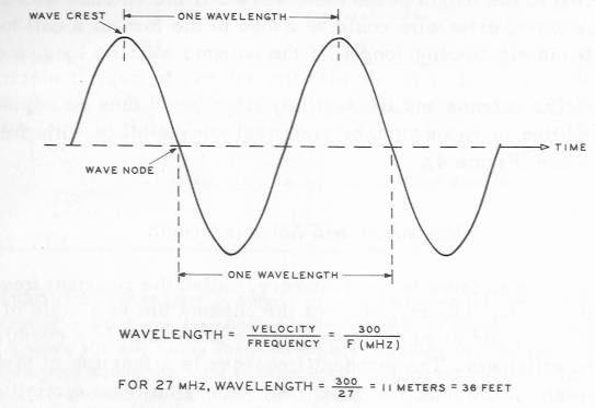
Figure 1 - A good way to visualize a signal as it travels through the air. We can now visualize an actual distance that a wave must travel to cycle. This distance is around 36 feet. If you convert 36 feet to meters you get approximately 11 Meters. This is why the CB band is sometimes called 11 Meters!
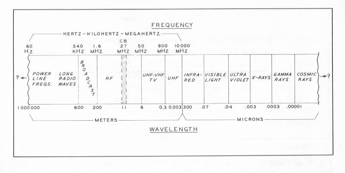
Figure 2 - A chart to show the relationship between the CB band and others. On the left the chart starts out with power line frequencies (60 Hz), AM Broadcast (1MHz), the CB band (27MHz) and goes all the way up through TV,FM Radio, Cellular Phone, Microwave to visible light frequencies. Lower frequencies have long wavelengths and high frequencies have short wavelengths.
Antenna Basics
How Antennas Work In General
When your transmitter puts a current (Radio Frequency (RF) energy) into an antenna, your antenna responds by producing a magnetic field surrounding the antenna (this is the signal). When this magnetic wave strikes another antenna (the receiving station antenna), it induces a current on the receiving antenna surface (that current is then converted by the receiving stations receiver to sound).
The length of the antenna structure plays an important role.
The magnetic field that your antenna puts out will produce an electric current on any metal surface that it strikes, however if the metal that the signal strikes has a length relation to itself the induced current will be much stronger on the object. We stated before that as a CB signal travels through the air, it completes a cycle in approximately 36 feet. For instance, if the object that the magnetic wave strikes is 18 feet long (1/2 wave length), 9 feet long (1/4 wavelength) or 36 feet long (1 full wavelength), then the induced current will be much higher than if the signal struck a metal object that was not some appreciable fraction of the wavelength of the signal. If you have ever heard people say they want to "tune" their antenna, they usually mean make it have a length relation to frequency they are trying to receive.
This has a special name, it as known as antenna resonance.
Every antenna has at least one exact resonance point.
Antenna resonance is the frequency (in MHz) where the antenna is in a state of electrical balance, which is determined by the length of the antenna (every antenna has an exact frequency it is resonant on). To use some numbers to demonstrate what we are explaining here, let us look at a very simple formula. You can calculate the distance of a wavelength in freespace for any frequency using this formula:
One Wavelength, in feet = 984 / Frequency in Megahertz (MHz)
Lets look at an example:
CB Channel 40 uses the frequency 27.405MHz.
One Wavelength for 27.405, 35.906 Feet = 984 / 27.405
So we want to make a antenna that is resonant on channel 40 and not too large in size. Lets cut a straight piece of aluminum rod to be 1/2 a wavelength long. One Wavelength for 27.405 is 35.906 feet (from the formula above), and we want 1/2 of that, or 17.593. So, we cut our piece of aluminum rod to 17.593 and we have made an antenna that resonates on 27.405 (or close to that). This piece of rod should pick up (receive) on channel 40 (27.405Mhz) well.
Ok, now lets look the most basic antenna most CBers are familiar with, the 102" whip, also known as the 1/4 wave whip. Why is it known as the 1/4 wave whip? As we can see if we get out our calculator, 102 inches is approximately 1/4 of 35.906 feet (1 wavelength). This antenna should also perform well on the CB band because its length relates to that 36 foot wavelength signal we are trying to receive!
To further simplify things, we have been speaking strictly about receiving - but these same principles apply to transmitting. Our antenna also transmits a strong signal if the antenna we are transmitting through is resonant on the frequency on which we are transmitting.
Tech Tip
Use a device called a Grid Dip Oscillator
to determine the resonance frequency of an antenna.
This brings us to our next topic - Bandwidth. Most of us use multiple frequencies when we use out radios. So, does this mean our antenna only works good at one frequency, the resonance frequency? No! Our antennas actually perform well over a range of frequencies. Most commercial CB antennas are designed to operate well over the 40 channels (that is a frequency range from 26.965 - 27.405 MHz). So, if you use your radio on all those frequencies it would be best to make it resonant in the middle around channel 20 or so (27.205 MHz). If you talk only on a certain channel then set it up for the frequency that you use most. The term that is important here is bandwidth or how much band your antenna works well over. For example if your antenna works well over the 40 channels then your bandwidth is 27.405 - 26.965, or .44 One method of judging how well (efficiently) your antenna is working is by measuring SWR.
SWR
To understand SWR or Standing Wave Ratio, we must first understand a few other properties all antennas have. You may have heard the terms radiation resistance, impedance, input impedance, feedpoint impedance. These terms are all referring to the same property of an antenna. When we think of the term resistance we usually think of some type of force that acts (or impedes). Do not confuse DC resistance with with radiation resistance. This is a totally different concept. You can not measure your antenna's impedance by using a Ohm meter on it! Impedance in antenna terms refers to the ratio of the voltage to current (both are present on an antenna) at any particular place on an antenna. This ratio of voltage to current is different on different parts of the antenna - which means that the Impedance is different on different spots on the antenna if you could pick any spot and measure it.
In formula terms:
Impedance of antenna = Voltage Field / Current field flowing within antenna.
Tech Tip
You can measure the feedpoint impedance of an antenna
by using a device known as a Noise Bridge.
This is great, but how does this relate to SWR? As you may or may not be aware of, most antennas are usually designed (and intended) to have an impedance at their feedpoint of 50 ohms. CB radios that are sold have antenna jacks on them that require they be hooked up to a 50 Ohm load (load - usually your antenna). This is why we use a 50 Ohm line (usually coax cable) to connect to the antenna. If we have an antenna not properly tuned close to 50 ohms or we used 75 ohm coax instead of 50 ohm coax a mismatch condition occurs. Basic laws of electronics dictate that if these impedance's (antenna jack, coax and antenna impedance) do not match then maximum power is not transferred. There are all kinds of situations that could cause a mismatch beside what I gave as an example. Smashed coax, bad connections, incorrect antenna assembly, mistuned antenna (incorrect antenna length) and objects too close to antenna are some other common causes.
What happens if there is a mismatch? At this point, lets just say that the antenna isn't tuned right, at the connection of the coax to the antenna, part (or all) of the wave is reflected back down the line. The amount of the wave reflected back depends how bad the mismatch is. The combination of the original wave traveling down the coax (towards the antenna or opposite during receive) and the reflecting wave is called a standing wave. The ratio of the two above describe waves is known as the Standing Wave Ratio (aka SWR). Generally you want a low SWR, preferably less than 2:1. In some mobile installation note that it is not possible to get the ratio lower than this without using a special matching device. This is because the impedance of most mobile antennas are lower than 50 ohms. In general, an SWR of 1:5 is fine! This is an area of battle for most antenna experts. Some strive to achieve a 1:1 ratio that indicates a maximum power transfer through their antenna system.
Tech Tip
You can use a device known as a SWR bridge to read the SWR of your antenna system. Most high end radios come equipped with one. If your radio does not have one, they are inexpensive and fit in line on the coax between your radio and the antenna
Back To Bandwidth
Now how can you use SWR to tell how broadbanded your antenna is? You can plot your SWR reading similar to the one in figure 3. Generally for base antenna use, a SWR over 2:1 indicates that the antenna is no longer performing efficiently - so the amount of band you can cover while keeping a SWR under 2:1 is considered your antennas bandwidth. You should center your lowest SWR reading on the channel you use most, or around channel 20 if you use them all. A few factors determine how broadbanded an antenna is. One of the main factors that I always keep in mind is conductor size of the antenna. For instance, if you made an antenna from wire, it would be less broadbanded than if you made it from larger tubing. The outside diameter is the primary concern, RF energy (on 11 Meters) travels on the "skin" or outside of the wire only. Another advantage to using larger conductor size on an antenna is it increase the amount of power it can handle safely (how many watts of transmit power it can handle).
Larger sized elements (larger tubing or wire) does not provide more gain. This is antenna manufacture propaganda and is totally false...thicker elements only serve to widen antenna bandwidth and up the power handling capability of an antenna system.
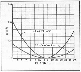
Figure 3 - This is a way to chart your antenna's SWR. Make a graph similar to this. Then make a reading on channel 1, and record it. Do it for each of the the channels. This is a good method to look at your antennas bandwidth. The graph shows to sample readings that you could expect from a 4 element beam, and a 5/8 Wave antenna.
The 1/2 Wavelength Dipole Antenna
When the first radio experimenters were first trying out their systems, they would just hook their transmitters up to long, high pieces of wire. It was later discovered that relating antenna length to frequency which one was transmitting and receiving on resulted in an antenna that worked many many times better than random pieces of metal. One of the first resonant antennas discovered was the 1/2 Wave dipole. The basic 1/2 Wave dipole is pictured in figure 4. If you wanted to make a dipole antenna to use on the 11 Meter band (CB), you would just make each leg a 1/4 Wavelength, right? Almost! Notice above how, I always spoke of terms of the Wavelength if it was traveling through the air. In other mediums (wires, earth (CB waves do not penetrate the ground far), coax) the wave travels slower than if it was traveling through the air. However the wave still completes its cycle in the same amount of time, but it didn't travel as far to do so. In other words the wavelength of a signal is shorter when traveling through wire, coax and your antenna. This is not a major concern, just be aware that is why the following formula is readjusted.
1/2 Wavelength, in feet = 468 / Frequency, in MHz.
For Channel 40 (27.405MHz) 17.077 = 468 / 27.405
Each Leg of the dipole would be a 1/4 wave or 17.077 / 2 = 8.386
Notice, above in the air a 1/2 wavelength would be 492 (1/2 of 984), but since the signal is traveling through wire instead of through the air, we must adjust our formula for calculating 1 wavelength (of a wave traveling through #12 Copper wire, not the plain old air). We are going to use this antenna to demonstrate a few other properties antennas have. First, lets examine the impedance of this antenna. If you place the connections in the middle you actually end up with a feedpoint impedance around 70 ohms at its resonance frequency. So as you can see, using this antenna, you are already looking at a SWR no lower than 1:3:1 (because of the mismatch of mating 50 Ohm Coax to a 75 Ohm antenna). Bandwidth of this antenna is largely dependent on how large the wire or tubing's outside diameter is. Lets introduce a new important antenna property, its radiation pattern (also known as polar plot or near field pattern)
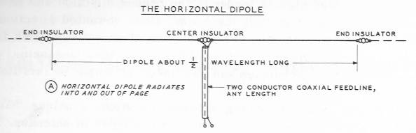
Figure 4 - The 1/2 Wavelength dipole antenna.
Radiation Pattern
Figure 5 shows the radiation pattern of a dipole antenna as if we were up in the sky looking directly down on the antenna from above. A radiation pattern is a visual representation of how an antenna concentrates (distribute is another way of saying it) its signal. The plot of the 1/2 wave Dipole (sometimes called the polar plot) is shaped like a figure 8 pattern. This antenna actually has gain, that is, signals coming from the front and rear are stronger than signals coming in off the ends.
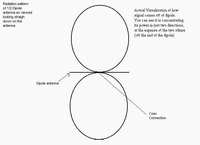
Figure 5 - Radiation pattern for a 1/2 wave dipole antenna.
Gain - Often misunderstood by radio operators!
Antenna gain is used to indicate the increase in power of one antenna (when transmiting or receiving) as compared to another antenna. Gain is actually a ratio of power levels and is stated in decibels, often abbreviated "db". So how do we use this number? Keep in mind I said "used to indicate the increase in power of one antenna as compared to another antenna.". So, how much gain does your antenna have compared to say, an actual coat hanger? Probably a lot! We know that a coat hanger could not be much of an antenna. But when using db gain to rate an antenna you must know what the reference antenna is!
It is important to note that antennas are passive, they do not "amplify" signals (or effect transmitted audio levels!), they merely re-distribute the power that they get to achieve gain. They have no effect on the "modulation" or audio quality of your radio! There are a few antenna manufactures that claim things like their beams, "have the best modulation". This is plain silly, over imaginative advertising.
Now, knowing something about the dipole (one of the most basic antennas) we can use it to compare antennas. If someone said, it has "6db over a dipole" or "6db, reference antenna is a dipole", it would have meaning! Lets look at two radiation patterns at the same time, to see how one antenna achieves gain. It will become obvious how it works once you see it, check out figure 6.
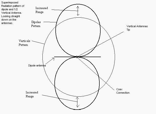
Figure 6 - How antennas achieve gain. You can see that the dipole antenna concentrates it signal, making it stronger in two directions. The vertical on the other hand, spreads the signal out evenly, resulting in a weaker signal, but with even coverage. The increased range comes from the dipole having gain over the vertical! The dipole uses energy off its sides and puts it in the two main lobes (the two parts of the "figure 8" pattern) You can see how gain translates into better signal range, by looking at the "increased range" marking on the diagram.
There is another "antenna" that people use give good honest gain figures over. It is known as the isotropic radiator, an antenna that exists only in theory. If we visualize the radiation pattern in 3D, we can see this antenna is radiating equally well in every direction. It is even transmitting straight down, straight up....all with the same intensity. You could picture it like a sphere (a perfectly round ball), the signal emits from the antenna (which would be at located at the exact inside center of the sphere) equally well in all directions. On planet earth however, this is not possible! The effect of the ground and other object alter the pattern of antennas on earth, and even if we designed an antenna to radiate like this, it would never work unless we took it out to space where there would be no objects (like the ground for instance) to interfere with it. Since it does not favor any particular direction, an isotropic radiator has a gain of Zero (0db).
So then, even our lowly dipole has gain over an isotropic radiator. How much you ask? Better sources say that a dipole has 2.1 db gain over an isotropic radiator. Then, if I tell you I have a antenna that has 6db gain over a isotropic radiator then, you know also that it has 3.9db over a dipole (6 - 2.1).
Great! So, how can I use this term gain? I have read many discussions on gain. The rule of thumb is that for every 3db of improvement you add to your antenna, it results in an effect that is noticeable to receiving stations (when transmitting, this goes for receive too). Any db less than 3 indicates an improvement that not appreciable (really detectable). Do not discount gain improvements under 3db...sometimes .5 of a db means hearing or not hearing a station!
Lets look at an example, say your current antenna has 9db of gain over a dipole. You really want to get a new antenna that is advertising 12 db over and isotropic. Really, your not going to see an improvement because we know that the advertised antenna really has a gain of 9.9db (12 - 2.1) compared to a dipole. Therefore, an improvement of .9db for the new antenna! Not a worthwhile gain especially if the new antenna is costly! A word to the wise...do not use advertised gain figures, instead consult this page or an antenna book to see what type of antenna design it classifies as and really see how much gain it has.
So, when you go to examine gain figures, manufactures should be stating a reference antenna. Usally if the gain figure is over a dipole you will see "dBd" for gain over dipole and "dBi" for gain over an isotropic. In all honestly, use all manufactures gain figures with care. Its better to figure out the antenna type (what specific design they are using), then consult this website or an antenna handbook to find out the real gain of the antenna. Gain figures today are so over inflated they are practically useless!
As another point, doubling your power (how many watts you use) results in improvements of 3db! We are not comparing antennas here, but this 3db is an improvement compared to our original signal running half the wattage. So, why bother with big antennas? Well, you might be transmitting further, but your receive range is unchanged! You could actually "out talk your ears", meaning people can hear you but you can not hear them! High gain antennas improve both transmitt and receive! You can't talk to people you can't hear!
An example, if you are running 20 watts, you would need to jump up to 40 watts for anyone to hear any difference (a 3db improvement) compared to when you were using 20 watts. So as you can see, once you are running higher wattage (over 100 watts), you must make large increases for other stations to notice a difference.
Not only is this a bad idea because it gets expensive, it is not necessary when using a good antenna! How is this possible? Well, if you are using 500 watts and you would like to get a 1000 watts amplifier, you could alternatively use an antenna that has 3db more gain than your current antenna and achieve the exact same effect, a signal that is louder to the receiving station!
As a precaution, I am going to cover most types of commercial CB antennas, and even if i do not, you will be able to pick out its type and figure out its gain. Unfortunately antenna technology on the HF bands (where 11 meters is located) has not improved all that much over the years. Antennas are constructed better today and optimized, but many of the antennas used in the 1970s are still the best!
Tech Tip
You can measure the radiation pattern of your antenna
by using a device known as a Field Strength Meter.
Polarization
The last fundamental theory we must understand is polarization. Do not be scared off, this theory was NOT saved till last because it was more difficult to understand! It is just as easy as any of the other concepts! A radio wave is actually made of up two fields, one electric and one magnetic. These two field are perpendicular to each other, shown in figure 7. The sum of the two fields is called the electro-magnetic field. Energy is transferring back and forth from one field to the other - This is what is known as "oscillation".
We are interested in one field primarily here - the electric field. Its position and direction with reference to the earths surface (the ground) determines wave polarization. Below, are two figures you can click on for an animated demostration.
Do not think these animations are an actually representation of a signal, they are to merely demostrate how the electric field is parallel to the radiating elements.
Horizontal polarization - The electric field is parallel to the ground.
Use back button to return to this page
Vertical polarization - The electric field is perpendicular to the ground.
Use back button to return to this page
In general, the electric field is the same plane as the antenna's element (antenna element is that actually metal part of the antenna that is doing the radiating). So if the antenna is vertical, then the polarization is vertical. The horizontal dipole in figure 3 is horizontally polarized. In figure 8, this is a vertical arrangement for a dipole, and its polarization is consequently vertical. It is important to note that the 1/2 wave dipole in a vertical position has a different radiation pattern (and consequently different gain over an isotropic) than the 1/2 wave dipole in the horizontal position. When most people talk about a dipole, they usually mean a 1/2 wave dipole in the horizontal position.
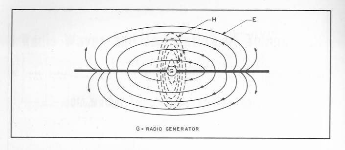
Figure 7 - Makeup of an Electro-Magnetic Field
Waves do not have to be either horizontal or vertical. This is merely an arbitrary setup. Antennas are arranged like this so that others can orient their antennas in a similar matter. These terms horizontal and vertical are in reference to the earths surface, take away the ground, say go into outer space and these terms would have no meaning! This is why we arrange our antennas for either a horizontal or vertical polarization though.
For instance, if the receiving antenna is receiving a signal that does not have the same polarization of itself, then the signal is reduced about 20db (almost 7 times) compared to if the signal had the same polarization as the receiving antenna. Some operators turn their beams at a 45 degree angle trying to achieve an in between polarization. This is just an old trick, that sometimes works out good.
The thing is, as our signals travel they usually reflect off of objects, and the field can change polarization! So your signal may end up loud and clear to another station even if you are not using the same polarization as each other because the signal may be bouncing off some object (a water tower for example) that might be flipping the polarization before it gets to the other station!
More people choose horizontal polarization for DXing because receiving using horizontal polarization is generally more quiet. This is because most man made noises (interference) are vertically polarized. There is no proof that horizontal waves are better for "skip" signals.
There is one special polarization known as Circular polarization. It should be of special interest to antenna experimenters! As the was travels it actually spins, not maintaining a set polarization but covering every possible angle in-between. This is good because it helps reduces signal fade (QSB) and flutter during DX contacts. It can either be right handed or left handed circular polarization depending on which way its spinning (think of it spinning clockwise or counter-clockwise as it leaves the antenna) I will detail how to make your beam radiate circular polarization under "Performance Tips" - only for beams capable of both vertical and horizontal polarization.
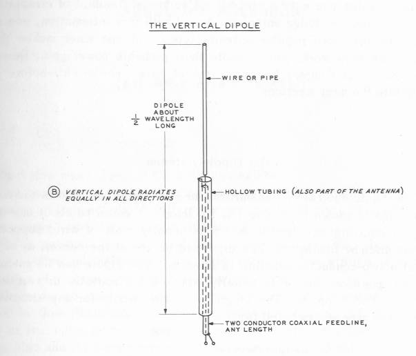
Figure 8 - The dipole in a vertical configuration.
In conclusion
Use back button to return to this page
We have covered a lot of antenna theory here. I arranged it to flow as logically as possible. I have also simplified several issues, so that you could get the needed ideas down quick. It might be necessary to go back and re-read this section to thoroughly understand it. If you feel like there is a section that is confusing, or just plain makes no sense, email me - that's what its for. If what you read was really interesting to you and you want to know more, there are several books you can read that are great! Antennas are like cars, some folks want to have the best (me included). It pays to learn all the antenna principles! These books are essential readings!
"The Truth About CB Antennas"
William Orr, W6SAI
The ARRL Antenna Handbook, any edition
Copyright © 2005 . Larry's Web Pages. All Rights Reserved