
11 Meter Antennasl
Coax Basics
Coax
Most CB and HAM radio operators use coaxial (coax) cable to feed their antenna. Another name for the cable you use to hook your radio to your antenna is "feed line". Feed line is a generic term for all types of cable including coax. Coax has been around for a long time and became very popular with Radio Amateurs after World War II, when army surplus stores were filled with miles of coax cable. This is one of them main reasons why we use coax today, it became such a trend of sorts. Coax cable consists of two concentric wires, as shown in figure 1. It is important to note that coax cable is unbalanced, no current flows on the outside shield of the cable. This is in comparison other types of feed line that are balanced such as twin-lead, which you may be familiar with from your old TV antenna. Figure 1 shows a close up of the end of coax, and its makeup.
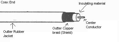
Figure 1 - Close up view of coax.
Coax has several advantages. You do not have to be careful what type of metal objects you run your coax over like you do twin-lead. It is even possible to bury some types of Coax, if the outer jacket is suitable. Its major disadvantage is that some types of coax have high loss at CB frequencies and get even worse as SWR increases. Usually companies rate their coax in decibels (db) of attenuation per 100 foot lengths. So at a given frequency, if you are using exactly a 100 foot length, you would incur a loss of however many db's the manufacture states. Here is a chart of the losses for the most common types of coax used for CB service:
Coax |
Attenuation in db per 100 feet (On 27MHz) |
Velocity Factor |
Description |
|---|---|---|---|
| RG-8 | 1.15 dB |
.66 |
50 Ohm coax |
| RG-59 | 2.0 dB |
.66 |
75 Ohm coax |
| RG-8/U Foam | 0.85 dB |
.80 |
50 Ohm coax, Foam Dielectric |
| RG-59/U Foam | 1.5 dB |
.79 |
75 Ohm coax, Foam Dielectric |
| Belden 9913 | 0.7 dB |
.84 |
Premium 50 Ohm coax |
| 1/2" Hardline | 0.35 dB |
.81 |
Special coax, expensive! |
| RG-8X (Mini-8) | 1.2 dB |
.78 |
Small 50 Ohm coax. Perferred over RG-58. Recommended for mobile installations. |
| RG-58 | 2.35 dB |
.66 |
50 Ohm coax |
| RG-213 | 1.35 dB |
.66 |
50 Ohm coax. |
| RG-11/U Foam | 0.85 dB |
.80 |
75 Ohm coax. |
| RG-11/U | 1.35 dB |
.66 |
75 Ohm coax. |
As you can see, some coax has high loss. Loss is RF energy that the coax turns into heat or "leaks" instead of passing on to the antenna (or to the receiver from the antenna). The lower the db of attenuation the better the cable is. Think of cable loss as negative gain! The higher the attenuation, the less efficient our antenna system is.
Loss is primary dependent on the coax's shield and dielectric. The shield is the outer wire braid that surrounds the inside of the cable. A thick, tight braid results in less loss. Also, the dielectric (usually white), the plastic type material that separates the inside wire from the outside braid has an effect on cable loss. Cables that use foam dielectric, that is where the insulation is mixed with an inert gas, have very low loss. It is important to use quality low loss cable! As you can see from the chart, the losses can be quite high. You must make perfect connections at the coax ends or, even higher losses will occur. It is also important to note that old coax has high loss also. The cables properties break down over time,
resulting in very inefficient cable. If you are still using that coax from the 1970s, its time to replace it! New coax is manufactured better than the coax was in the 1970s also, so this newer cable should last a lot longer.
Two special cables are listed. One is Belden 9913. Belden is the name of the company that makes the cable and they call it "9913". It is a special coax that has two outside shields! The first is a foil material that is on the outside of the dielectric, then over that is the regular copper braid. As a result, the cable is very efficient (low loss) and also STIFF (though they now make a 9913F that is supposed to be flexible)! With low loss comes cost, this cable is expensive. The other special cable listed is hardline. This cable has a solid aluminum cover on the outside for the shield. It is thick, and very efficient---stiff (can't really bend it) and costly. It is used by cable TV companies. Since they run miles and miles of cable, they need low loss cable. Cable loss is still so bad, they still need to have amplifiers along the cables every few miles or so. You can see hardline on telephone poles if your area has cable. It is usually a silver cable about 3/4 inches in diameter.
I said before that loss becomes even worse as SWR increases. These attenuation numbers in the chart
are assuming a perfect 1:1 match. If your SWR is over 3:1, cable loss is horrendous no matter what kind of coax it is!
Coax Impedance
Again, the term impedance in "Coax Impedance" has different meaning...you can not measure it with your trusty Ohm meter. It is determined by the spacing (ratio) of the inner wire and outer braid. In CB service, the two impedance's mainly used are 50 Ohm and 75 Ohms.
Velocity Factor
Wow, doesn't that sound like a serious high tech term! You can be king nerd of your CB group if you know things like "velocity factor". Ok, ok we said before that waves travel different speed through different materials, if you missed it, its under the "1/2 Wavelength Dipole" Section of "Antenna Basics". Velocity factor is simply a number we use to determine how fast or slow a wave travels through coax. Different
Coax models have different velocity factors. Lets look at some numbers. Say we want to make a coax that is exactly 1/2 wavelength long (this means when the wave travels through the coax, it makes exactly 1/2 of a cycle while it travels from one end of the coax to the other). If this sounds confusing, better check out the "Antenna Basics" section. We will take our formula for figuring out 1 wavelength and modify it.
One Wavelength in coax, in feet = 984 * (Velocity Factor) / Frequency in Megahertz (MHz)
Ok, say we want a 1/2 wavelength RG-8/U Foam on channel 40 (27.405)
984 is for a 1 wavelength, so we want a 1/2 wavelength or half of 984, 984 / 2 = 492. Get the Velocity Factor from the table above for RG-8/U Foam, which is .80. Put these numbers into the formula:
1/2 Wavelength, RG-8UFoam, Ch.40 = (492 * .80) / 27.405
1/2 Wavelength, RG-8UFoam, Ch.40 = (393.6) / 27.405
1/2 Wavelength, RG-8UFoam, Ch.40 = 14.362343 feet
The length of coax is 14 feet 4 inches! Practice and see if you can get lengths for other coax types with different velocity factors. This will become important if you ever "stack" or co-phase antennas. You must cut certain length coax lines for co-phased antennas to work!
Assemble Your Coax Correctly
Bad connection cause loss. If you are going to solder connectors on the ends of your coax, be sure to do it right. You must have the right tools. Most Cbers and Ham radio operators think that they can solder on connectors to coax with their 25 Watt pencil tip soldering iron. You can't. You should use a high wattage iron, preferably over 100 watts. You must heat the connector up quick, so you do not damage the coax and connector, and the only way to do this is with a high wattage soldering iron. I am not going to go into detail of soldering on PL-259 connectors to coax but let you look at figure 2. Trim the coax carefully, do not nick the inside when cutting. And I have one big tip you do not want to forget, before soldering the PL-259 plug to the coax, do not forget to slide the PL-259 collar over the coax! I have done this so many times! Soon as you start working just slide that collar on, push it back far down the coax out of the way so it does not slide back off..you will thank me for this! If you solder the connector on without sliding the collar on, you will have to start over (the collar will not fit over the connector once it is soldered on)! After you are
done (or to check coax you suspect is shorted or bad) take an Ohm meter and check you coax as shown in figure 3.
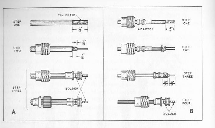
Figure 2 - How to solder on a PL-259 to coax.
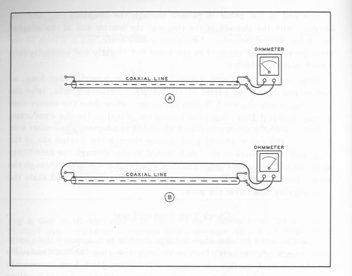
Figure 3 - How to check to make sure your coax is ok. This does not check for cable loss, it just makes sure the cable is not shorted or an open circuit.
When you are done, be sure to waterproof the ends of the cable. Wrap it in quality electrical tape (I like 3M electrical tape) or use a special wrap you can get at radio shack. Water will easily find its way into coax ends. Remember I said old coax has high loss? This is probably the number one way coax is ruined.
Why does my coax length affect the SWR of my antenna?
How many of you change the length of your coax to tune your antenna? One of my good friends said to me, "I think changing the length of the coax is the same as moving the gamma rod adjustment on my Moonraker 4". Sorry to say, this is not true. As most people will find, varying the length of coax to the antenna will vary the SWR that the SWR meter is reporting. Actually, SWR should remain relatively constant no matter how long the coax is or where it is placed on the line (if its 5 feet down the coax from the radio or 50 feet down the coax from the radio). In most cases, the cause of inconsistant SWR meter readings is from poor SWR meter design or component aging / failure. For the SWR meter to read consistant SWR readings on the coax, the meter has to have an impedance itself of exactly 50 Ohms. Any deviation of the SWR meter's self impedance (from 50 Ohms) from poor design or component aging / error / failure will cause slightly inconsistant SWR readings when the SWR meters position on the coax or length of the coax is varied. In practice, generally you will find varying the coax length seemingly effects the SWR reading. Most SWR meters (built into radio and external type meters) and impedance "humps" in coax lines and connectors will cause minor variations in SWR as jumpers and coax length are varied. In reality, the mismatch at the antenna's feedpoint / coax junction is unchanged. Therefore - the actual SWR is unchanged.
Another reason SWR could vary is from the situation where the coax is acting as part of the antenna. Not a favorable or normal situation. The signal is traveling back down the outside of the of the coax braid (note power should only be traveling on the inside on the coax braid). Therefore, the coax is part of antenna system and changing the coax length will change the SWR. This situation is more likely to occur in mobile installations. You can try to eliminate this situation (called "Common mode currents") by winding an "RF Choke". Wind about 6ft of RG-213 or RG-8 into a coil (6 to 8 turns). For RG-58 use 4ft with 6 to 8 turns. Wind the coax up, placing each turn right next to one another. Use electrical tape to secure turns together. You should place these as close to the antenna as possible. Right at the antenna coax connection point being optimum. Most times, you can verify that you have common mode currents flowing back down the coax by grabbing hold of the coax while transmitting and moving the coax around. You can watch the SWR waver by moving the coax while transmitting (don't speak into mic!). You have to do this with all the doors closed from inside the vehicle. SWR should waver, if you notice that SWR jumps rapidily between two values, you might have a intermitant (bad) connection in the connectors (PL-259s) on the coax. In most cases of "common mode currents", just grabbing the coax will cause the SWR to change.
The "RF choke" described above stops the signal from traveling back down the outside of the coax. The signal inside the coax is * u n a f f e c t e d * by the choke (contrary to what you may have heard about coiling up excess coax). Common mode current kills antenna efficieny. You could have a decent SWR and not realize half your signal is being broadcast into you car (result very poor antenna performance). If your linear amplifier causes serious problems with your car's computer, lights, etc....you may have common mode currents. If moving the coax around the vehicle results in SWR change, this is a good indicator you have common mode currents flowing back down the coax line.
This doesn't happen often with base station antennas. Most base antennas have some type of device that will decouple the antenna from the feedline (gamma match, balun, etc.). Make sure you run your feedling (coax) straight down from the antenna, taking care not to run close to antenna to prevent "common mode" currents which could still occur if coax is oriented in a way to pick up strong antenna signal.
Coax Length Issues Simplified
Question: What is the "correct" length of coax?
Answer: The shortest length that makes it from the radio to the antenna.
Question: Are there any exceptions to the above rule?
Answer: 75 Ohm harnesses for Co-phasing is the only exception.
Question: Why do most mobile antenna makers recommend 18 feet of coax?
Answer: You got me, they claim you should use 1/2 wavelength multiples of coax. 18 feet isn't even close to being a 1/2 wavelength in any 50 Ohm coax you will find. Check some commonly used coax using the above formulas. RG-58, the most commonly used mobile antenna coax length would have to be 12 feet to be a 1/2 wavelength. RG-8X would need to be 14 feet.
Question: Ok, seriously nerd, when I trim my coax it changes my SWR. You can't tell me it's not good to lower my SWR from 1.5 to 1.2 by taking off a few extra feet of coax.
Answer: Hey, I'm not a nerd! Go ahead, change your coax length. If you change coax length and it affects your SWR in minute amounts, everything is working fine. If your SWR was 2.5:1 and putting in a 4 foot jumper brought it down to 1.3:1, this large change indicates you have real problems...i.e. common mode currents (see above). Really, you should be changing the antennas length to alter SWR. NO special length of 50 ohm coax is going to fix or lower your SWR signficantly and/or boost performance. Period.
Question: I notice when I change coax length, my "modulation" needle jumps more / harder / faster when I talk. I get more watts out of the radio (verified by a watt meter) with certain lengths of coax. Is there a certain length that will allow my radio to put out the most power?
Answer: No, there isn't a magic certain length that will do this. Certain lengths of coax will allow your radio to "see" a load that it can couple with better which results in more power out of the radio / amp. Unfortunately, there isn't a good way to determine what length you need to allow the radio to put out the max wattage its capable of. I am only refering to newer solid state radios with transistors. Old tube radios usaually have devices built into them to tune the radios finals impedance to match that of the input end of the coax. If you want to accomplish the same effect with your solid state radio, pick up a device known as a "antenna tuner". The term antenna tuner is misleading because it doesn't actually tune the antenna - or take the place of tuning the antenna - it simply lets the radio couple to the antenna system with better efficiency. Other more appropriate names for the antenna tuner are the transmatch or feedline flattener. If your SWR is low (below 2:1), don't expect to notice a (performance) difference from using an antenna tuner.
Question: Why do so many people recommend using 1/2 wave mutiples of coax? Will it really hurt me if I take the time to measure a 1/2 wavelengh multiple of coax?
Answer: The idea of using 1/2 wavelength multiples of coax comes from the fact that the antennas feedpoint impedance is "mirrored" at the input of the coax when using the said length. Many operator make / made the assumption that was a good thing because it was just like having the antenna hooked right to the radio / SWR meter. If anything other than a 1/2 wavelength mutiple is used, the impedance the radio / SWR meter sees is the antennas feedpoint impedance transformed to some other value of impedance. So, if your antenna has a feedpoint impedance of 25 Ohms and you use a 1/2 wavelength wave length of coax, the radio will "see" 25 Ohms in the input end of the coax. If you were to use some other length, say a 1/4 wavelength of 50 Ohm coax, the radio would "see" an impedance of 100 Ohm. What consequences does this have? None. Whether the impedance is 25 Ohms or 100 Ohms, the SWR is STILL 2:1. No matter what the 50 ohm line length, the resultant SWR is still 2:1...at the antennas feedpoint, at the input end of the coax and at any and every point along the coax line.
Many operators take half the truth of transmission line theory and make up their own rules. If you have been reading my page since its inception, you know I used to be "uneducated" when it came to transmission line theory. Sorry to admit I thought coax length was important. It was drilled into my head by somebody I respect(ed).
This isn't the easiest part of CB to wade through. Hopefully I've covered this with enough detail to set everyone straight. Many beginner amateur radio operators and students have misceptions and make false extrapolations in tranmission line theory. There are many conditions that must be stated when simplifying things. I have made one assumption here. I have been assumming the coax loss is negligible. At CB frequencies this is a pretty safe assumption to make.
Question: Ok then, why is the length of 75 Ohm coax line important? If coax length doesn't matter, why is 75 Ohm coax different?
Answer: I've heard this a question more than once. The fact your radio has a 50 Ohm jack on it is the reason you use 50 Ohm coax. The antenna is designed to have a feedpoint impedance of 50 Ohms. When all the impedances match, maximum power is transfered from the radio, through the coax, out the antenna. Using coax with a (characteristic) impedance of 75 Ohms can potenially transform the antennas feedpoint into another value..another value such that the resultant SWR will vary with line length. This function is handy for matching antennas to the feedline that do not have feedpoint impedances of 50 Ohms. This is beyond the scope of this section, but antenna makers can specify certain lengths (1/4 wave) of 75 Ohm coax to achieve the proper match between radio and antenna. Again, this form of matching is not possible with 50 Ohm coax.
|
Copyright © 2005. Larry's Web Pages. All Rights Reserved